Chapter 二 technical specifications
1. The main technical indicators of the equipment
1.1 environmental conditions
Operating Temperature:-40℃~55℃; ,
Storage temperature:-40℃~65℃.
Operating relative humidity:≤90%(at 40±2℃).
Storage relative humidity:≤95%(at 40±2℃).
1.2 Vibration
Withstand sine wave vibration with frequency of (10~55) Hz and amplitude of 0.35mm.
1.3 Seismic strengthening
The seismic strengthening of the system meets the requirements of YD 5096-2016 Code for Seismic Performance Testing of Communication Power Equipment
1.4 Appearance, structure
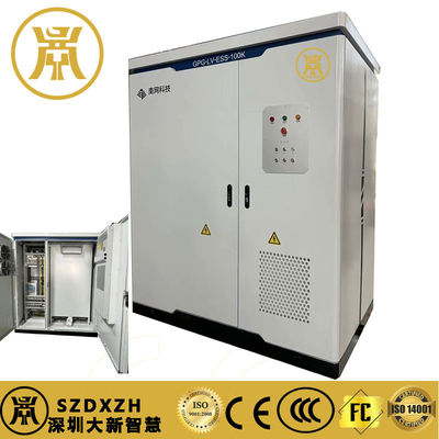
1.4.1 Shape.
Dimensions: 300mm (W) * 400mm (D) * 200mm (H)
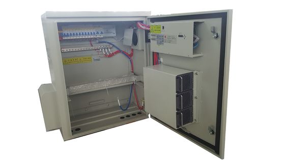
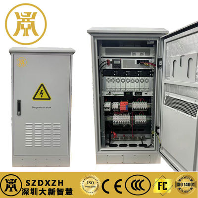
1.4.2 Input and output interfaces
From left to right: AC Input, Battery Connector, DC Load 3, DC Load 2, DC Load 1, Communication Port, Antenna Connector and Ventilation Valve
1.4.3 Schematic diagrams of indicator lamps
From left to right: green (running light), yellow (warning light), red (fault light)
1.4.4 Schematic diagram of mounting method.
Installation of derrick and flat installation
Flag mounted 80mm * 80mm
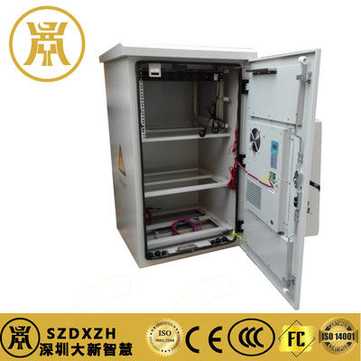
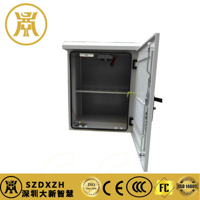
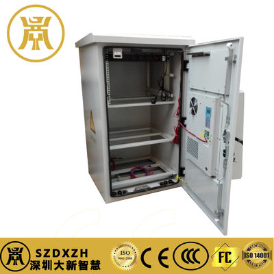
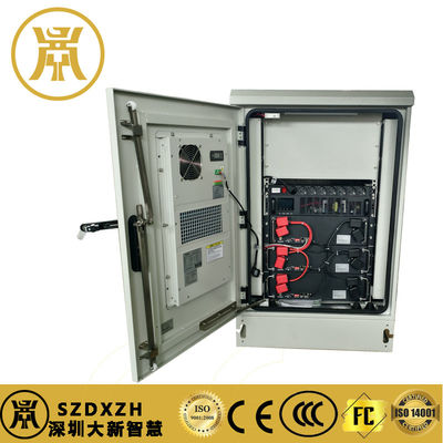
1.4.5 The overall effect of the appearance of the product
1.5 power supply technical requirements
5.1 Electrical performance
5.1.1 Input voltage range
AC 220V, rated voltage 220V, input voltage range: 176V~264V;
When AC input is 100Vac~175Vac, derate to output 1000W
Nominal value DC 240V/336V, rated voltage 378V, input voltage range: 260~400V (192V~280V).
When DC input is 140Vdc~240Vdc, derate to output 1000W
5.1.2 AC input power requirements
1) Rated frequency
The rated frequency is 50Hz.
2) AC frequency fluctuation range
The fluctuation range of input frequency is 50Hz ± 2.5Hz.
5.1.3 Input power factor
The input power factor of the system at different load factors satisfies the requirements of Table 1.
Input power factor table Table 1
input power factor at different loads Requirements
At 100% load factor , the >0.99
At 50% load factor , the >0.98
At 20% load factor , the >0.94
5.1.4 Input voltage waveform distortion rate
Input voltage waveform distortion rate is not more than 5%.
5.1.5 Input current total harmonic distortion
The input current harmonics of the system at different load factors satisfy the requirements of Table 2.
Input Current Total Harmonic Distortion Table Table 2
total harmonic distortion of input current at different loads Requirements
At 100% load factor ≤5%
At 50% load factor ≤8%
At 20% load factor ≤10%
5.1.6 Input no-load losses
No load loss of equipment is less than 1% (20W) of rated power.
5.1.7 Output voltage setting range value ,
The nominal value is - 48V, the output voltage range is 43V-57V, and the voltage stabilization accuracy is ± 0.5%.
5.1.8 efficiency
The output nominal value - 48V efficiency meets the requirements in Table 3.
Nominal Output Values - 48V Efficiency Table 3
load factor Efficiency
100% load ≥95.5%
50% load ≥96%
20% load ≥93.5%

 Your message must be between 20-3,000 characters!